Difference between revisions of "SB-SOM: Connectors: P10"
| Line 10: | Line 10: | ||
:* A DVI/HDMI display at connector '''J5'''. | :* A DVI/HDMI display at connector '''J5'''. | ||
:* An LVDS display at connector '''P11''' (if implemented through parallel RGB interface with your specific SB-SOM board). | :* An LVDS display at connector '''P11''' (if implemented through parallel RGB interface with your specific SB-SOM board). | ||
| − | :* An LCD display at connector | + | :* An LCD display at connector P10. |
{{note|Selection of the parallel RGB interface path (DVI/LVDS/LCD) must be implemented through system-on-module software.}} | {{note|Selection of the parallel RGB interface path (DVI/LVDS/LCD) must be implemented through system-on-module software.}} | ||
Revision as of 06:57, 25 May 2016
Description
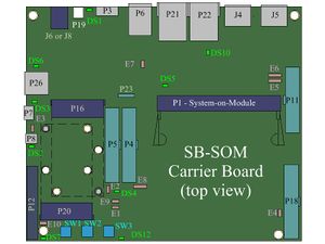
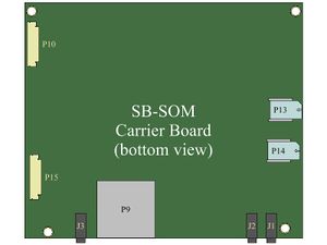
Connector P10 is a 40pin FPC connector (output) designed to drive an LCD panel with resistive touch capabilities. Connector P10 is available only in case parallel RGB interface is available at "PDISP" pins of system-on-module. Connector P10 allows seamless connection of the SHENZHEN STARTEK ELECTRONIC TECHNOLOGY KD050C-1A-TP LCD panel.
Only one of the following SB-SOM display interfaces can be driven with the system-on-module parallel RGB interface at a time. Driving more than one of the below simultaneously is in most cases unsupported.
- A DVI/HDMI display at connector J5.
- An LVDS display at connector P11 (if implemented through parallel RGB interface with your specific SB-SOM board).
- An LCD display at connector P10.
| Selection of the parallel RGB interface path (DVI/LVDS/LCD) must be implemented through system-on-module software. |
| Please refer to SB-SOM carrier board schematics and system-on-module hardware reference manual for pin functions, connector pinout and other details on your specific system. |
More Details: Connector J5, Connector P11.
Connector Data
P10 connector Manufacturer MFG P/N CVILux CF20-401D0R0-LF

