CL-SOM-iMX8Plus: Evaluation Kit: Hardware Guide
Contents
Overview
Terms and Definitions
- SoM – System-on-Module.
- SBC – Single Board Computer.
- CL-SOM-iMX8Plus– System-on-module product based on the NXP iMX8M-Plus SoC. More information here.
- SB-iMX8Plus – A carrier board, intended for evaluation and development with CL-SOM-iMX8Plus. More information here.
- CL-SOM-iMX8Plus Evaluation kit – A combination of CL-SOM-iMX8Plus SoM and SB-iMX8Plus carrier-board accompanied by a set of accessories. More information here.
Additional resources
- All additional materials for CL-SOM-iMX8Plus and SB-iMX8Plus are available here.
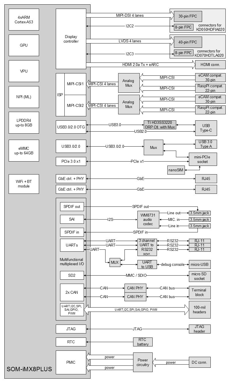
Block Diagram
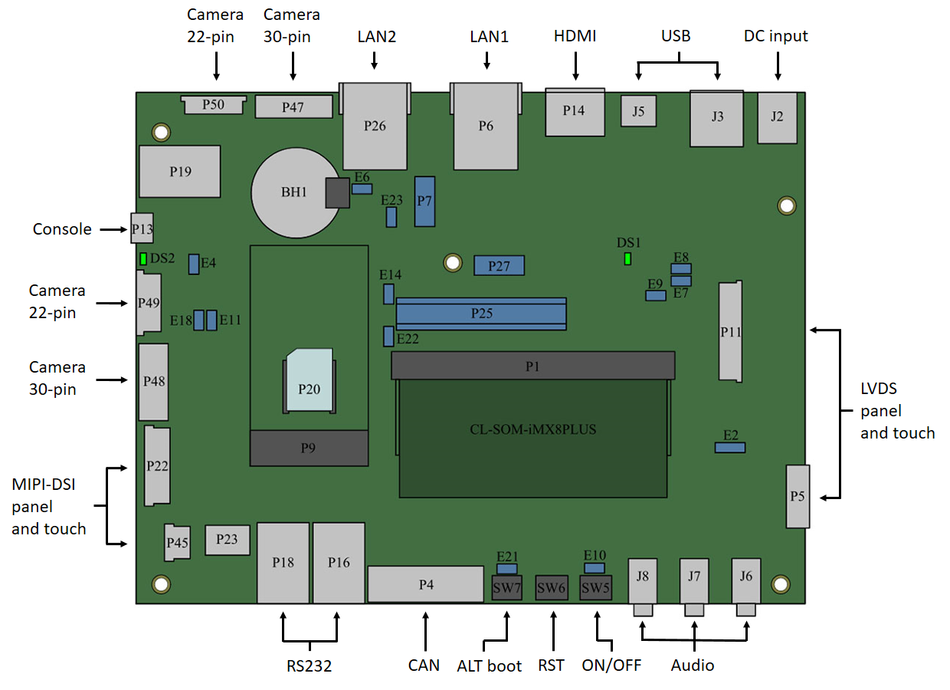
Connector Locations
Interfaces and Functions
DC Power
SB-iMX8Plus main power is provided with 12V DC power supply included in the evaluation kit. Adapters for European AC and US AC outlets are included. Connect the power supply to connector J2.
Serial Console
To begin using serial console connect your host PC to the micro-USB connector P13 using the USB cable from the evaluation kit and make sure that jumper E4 is open.
Display
HDMI
SB-iMX8Plus supports HDMI output on connector P14. Connect to standard monitor using an HDMI cable.
MIPI-DSI
SB-iMX8Plus supports direct connection with the Startec KD050HDFIA 5" MIPI-DSI LCD panel.
Connect the display data cable to connector P22.
Connect the display touch-panel cable to connector P45
LVDS
SB-iMX8Plus supports direct connection with the Startec KD070HDTLA020 7" LVDS LCD panel.
Connect the display data cable to connector P11.
Connect the display touch-panel cable to connector P5
USB
SB-iMX8Plus features two USB3.0 ports that are derived from the i.MX8M Plus USB sub-system:
- Connector J5 – USB type-C connector
- Connector J3 – USB3.0 host, type-A connector
SD card
SB-iMX8Plus supports SD card storage through micro-SD socket P23.
Ethernet
SB-iMX8Plus provides two Ethernet ports via RJ45 connectors:
- P6 – primary Ethernet port
- P26 – secondary Ethernet port
Wireless
WiFi/Bluetooth
For WiFi or Bluetooth operation connect the WiFI/BT antennas (included in the evaluation kit) to CL-SOM-iMX8Plus on-board connectors ANT_A and ANT_B.
Cellular
Cellular modems in mini-PCIe form-factor can be plugged into mini-PCIe socket P9. For modem operation:
- Insert an active SIM card to socket P20
- Insert the cellular modem into socket P9
PCI-Express
Mini-PCIe modules can be installed into the SB-iMX8Plus mini-PCIe socket P9. Full / half size mini-PCIe modules are supported.
NOTE: USB port on mini-PCIe socket is multiplexed with the USB port on connector J3. Jumper E14 must be installed for correct operation of mini-PCIe.
CAN bus
Two independent CAN bus interfaces are available via terminal block P4.
Please refer to CL-SOM-iMX8Plus reference guide and SB-iMX8Plus schematics for details.
Camera
SB-iMX8Plus is compatible with the e-CAM and Raspberry Pi camera modules.
Each of the two independent MIPI-CSI channels is routed to 30-pin and 22-pin connectors through analog multiplexers. Connector multiplexing selection is done with jumpers:
- MIPI-CSI1 - jumper E18 selects between 22-pin connector P49 and 30-pin connector P48
- MIPI-CSI2 - jumper E23 selects between 22-pin connector P47 and 30-pin connector P48
Multi-functional signals access
UART
UART interface is available via header P27.
Please refer to CL-SOM-iMX8Plus reference guide and SB-iMX8Plus schematics for details.
SPI
SPI interface is available via header P25.
Please refer to CL-SOM-iMX8Plus reference guide and SB-iMX8Plus schematics for details.
I2C
I2C interface is available via header P25.
Please refer to CL-SOM-iMX8Plus reference guide and SB-iMX8Plus schematics for details.
GPIO
GPIO signals is available via headers P25 and P27.
Please refer to CL-SOM-iMX8Plus reference guide and SB-iMX8Plus schematics for details.
System
Reset
Pressing the reset button SW6 triggers system hardware reset.
Boot Sequence Selection
Pressing and holding the alt-boot button SW7 during power-up or hardware reset forces CL-SOM-iMX8Plus to boot firmware from an SD card in socket P23.
Power ON / OFF
Long press on the Power On button SW5 shuts down the device.
RTC
RTC is implemented on CL-SOM-iMX8Plus and receives power from coin-cell battery BH1.
Jumper E6 must be shorted for correct RTC operation.
JTAG
JTAG interface is available via header P7.
Please refer to CL-SOM-iMX8Plus reference guide and SB-iMX8Plus schematics for details.
Jumpers Summary
Jumpers:
- E4 - force debug over RS232 instead of USB.
- E6 - RTC power.
- E7, E8 - 12V input current measurement.
- E9 - 12V input main power enable.
- E11 - carrier board EEPROM write protect.
- E14 - USB multiplexing between mini-PCIe socket P9 and USB connector J3.
- E21 - force CL-SOM-iMX8PLus to perform firmware boot from SD card.
Default state:
- Jumpers E6, E9 are populated;