Difference between revisions of "IOT-GATE-RPI4: Getting Started"
(Created page with "= Quick Setup = * Connect HDMI monitor to the IOT-GATE-RPi4 display output using a standard HDMI cable. * Connect USB mouse and keyboard devices to the IOT-GATE-RPI4 USB conn...") |
|||
| Line 1: | Line 1: | ||
= Quick Setup = | = Quick Setup = | ||
| − | * Connect HDMI monitor to the IOT-GATE- | + | * Connect HDMI monitor to the IOT-GATE-RPI4 display output using a standard HDMI cable. |
* Connect USB mouse and keyboard devices to the IOT-GATE-RPI4 USB connectors. | * Connect USB mouse and keyboard devices to the IOT-GATE-RPI4 USB connectors. | ||
* Insert the AC power supply blade into the power supply unit. | * Insert the AC power supply blade into the power supply unit. | ||
* Insert the power supply plug into the IOT-GATE-RPI4 input jack. Turn the power plug clockwise to lock the plug. | * Insert the power supply plug into the IOT-GATE-RPI4 input jack. Turn the power plug clockwise to lock the plug. | ||
| − | * IOT-GATE- | + | * IOT-GATE-RPI4 will automatically boot into the OS |
= IOT-GATE-RPI4 Overview = | = IOT-GATE-RPI4 Overview = | ||
| Line 38: | Line 38: | ||
= SIM card installation = | = SIM card installation = | ||
| + | * Power off the device | ||
* Remove the screw from the SIM/PROG tray-cover | * Remove the screw from the SIM/PROG tray-cover | ||
* Insert a SIM removal tool into the cover popping hole to pop the tray-cover | * Insert a SIM removal tool into the cover popping hole to pop the tray-cover | ||
* Place the SIM into the tray | * Place the SIM into the tray | ||
| − | * Carefully push the tray | + | * Mind the SIM tray orientation. You will need to turn the device upside down to keep the SIM from falling off the tray. Carefully push the tray cover back in |
* Close the SIM/PROG cover screw (optional) | * Close the SIM/PROG cover screw (optional) | ||
| + | * Restart the device | ||
: [[Image:Iot-gate-rpi4 sim-tray-cover.png|800px]] | : [[Image:Iot-gate-rpi4 sim-tray-cover.png|800px]] | ||
| Line 48: | Line 50: | ||
In case a monitor is not available, IOT-GATE-RPI4 can be used with a host PC console terminal. | In case a monitor is not available, IOT-GATE-RPI4 can be used with a host PC console terminal. | ||
| − | * | + | * Use standard USB-to-micro USB cable to connect host PC and IOT-GATE-RPI4. |
| − | * On your host PC, start a terminal emulation program ( | + | :* Plug micro USB end to IOT-GATE-RPI4's micro-USB debug console connector |
| + | :* Plug USB end to host's USB port | ||
| + | * On your host PC, start a terminal emulation program (e.g.'''minicom''' on a Linux host) with the following serial port settings: | ||
{| class="wikitable" cellspacing="1" cellpadding="1" border="2" width="500" style="text-align: center | {| class="wikitable" cellspacing="1" cellpadding="1" border="2" width="500" style="text-align: center | ||
| style= background-color:#ffffcc;" | '''Baud Rate''' | | style= background-color:#ffffcc;" | '''Baud Rate''' | ||
| Line 64: | Line 68: | ||
* Plug the power supply unit into an AC outlet. IOT-GATE-RPI4 will turn on and boot into Linux. | * Plug the power supply unit into an AC outlet. IOT-GATE-RPI4 will turn on and boot into Linux. | ||
* Use "pi" as a username and "raspberry" as a password as initial Linux account credentials. | * Use "pi" as a username and "raspberry" as a password as initial Linux account credentials. | ||
| + | |||
| + | = Additional Resources = | ||
| + | <br> | ||
| + | *[[IOT-GATE-RPI4: Raspberry Pi OS: How-To Guide|IOT-GATE-RPI4 Linux How-To Guide]] | ||
| + | * [https://www.compulab.com/products/iot-gateways/iot-gate-rpi4-industrial-raspberry-pi-iot-gateway/#devres IOT-GATE-RPI4 Resources] | ||
| + | * [https://www.compulab.com/products/iot-gateways/iot-gate-rpi4-industrial-raspberry-pi-iot-gateway/#accessories IOT-GATE-RPI4 Accessories Guide] | ||
| + | |||
| + | = Useful How-To Videos = | ||
| + | <br> | ||
| + | {{#ev:youtube|https://www.youtube.com/watch?v=Q_iGu8bjwaw|400|inline|I/O module replacement|frame}} | ||
| + | {{#ev:youtube|https://www.youtube.com/watch?v=x7mNuQcTtLU|400|inline|VESA / wall-mount bracket installation|frame}} | ||
| + | {{#ev:youtube|https://www.youtube.com/watch?v=1dszTXjgXqM|400|inline|DIN rail bracket installation|frame}} | ||
| + | |||
[[Category:IOT-GATE-RPI4]] | [[Category:IOT-GATE-RPI4]] | ||
Latest revision as of 08:27, 16 February 2023
Contents
Quick Setup
- Connect HDMI monitor to the IOT-GATE-RPI4 display output using a standard HDMI cable.
- Connect USB mouse and keyboard devices to the IOT-GATE-RPI4 USB connectors.
- Insert the AC power supply blade into the power supply unit.
- Insert the power supply plug into the IOT-GATE-RPI4 input jack. Turn the power plug clockwise to lock the plug.
- IOT-GATE-RPI4 will automatically boot into the OS
IOT-GATE-RPI4 Overview
Front panel
Back panel
Left and Right panels
Default antenna connector assignment
| Connector | Function |
| WiFi / BT | Wifi / Bluetooth antenna |
| WWAN | Main LTE antenna |
| AUX | Auxiliary GNSS antenna |
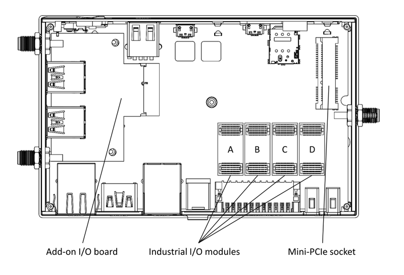
Service bay
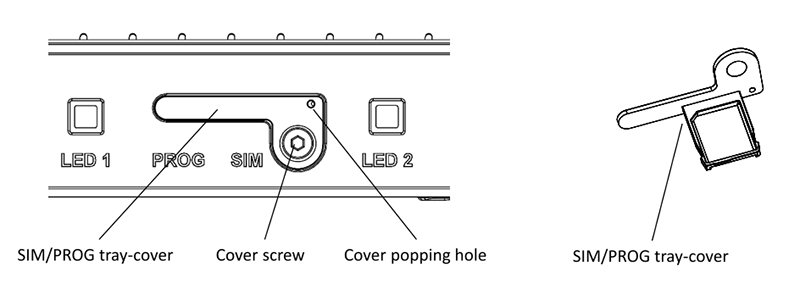
SIM card installation
- Power off the device
- Remove the screw from the SIM/PROG tray-cover
- Insert a SIM removal tool into the cover popping hole to pop the tray-cover
- Place the SIM into the tray
- Mind the SIM tray orientation. You will need to turn the device upside down to keep the SIM from falling off the tray. Carefully push the tray cover back in
- Close the SIM/PROG cover screw (optional)
- Restart the device
Headless Quick Setup
In case a monitor is not available, IOT-GATE-RPI4 can be used with a host PC console terminal.
- Use standard USB-to-micro USB cable to connect host PC and IOT-GATE-RPI4.
- Plug micro USB end to IOT-GATE-RPI4's micro-USB debug console connector
- Plug USB end to host's USB port
- On your host PC, start a terminal emulation program (e.g.minicom on a Linux host) with the following serial port settings:
| Baud Rate | Data Bits | Stop Bits | Flow Control |
| 115200 | 8 | NONE | NONE |
- Plug the power supply unit into an AC outlet. IOT-GATE-RPI4 will turn on and boot into Linux.
- Use "pi" as a username and "raspberry" as a password as initial Linux account credentials.
Additional Resources
Useful How-To Videos


